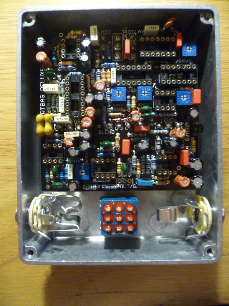
First up here is the populated board
Its a pretty serious build. I didnt read the manual properly (skim) before starting, but thanks to experience I populated the board exactly as described in the BOM, so it does work and everything can fit.

Resistors first - 1/4W 1% metal film mostly, 5% carbon for odd values. I used my multimeter to verify where it was important (5.6K for example).
Then the diodes, and the trimmers. Diodes, easy, trimmers, I recommend Tayda. These ones are exactly to spec size wise for Beans boards, and are ridiculously cheap ($0.16 IIRC). I bought a bunch of each value for future use.
After that, the sockets. I prefer the gold contact turned variety, but the standard ones are fine. Bear in mind the gaps with some of the resistors/capacitors is touch and go (see around IC for a good example) so take care with positioning. I seem to recall R8 and R60 being in the way a bit. Also, C34 and C40 can stop the IC being inserted fully, so watch out for that when socketing.
After all this I added my pots and switch.
Concurrently, I was marking and drilling the box. The culmination of which is this:
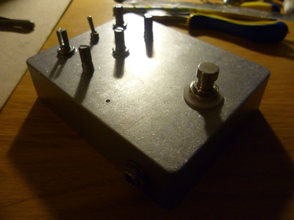
I drilled a pilot hole for the Overload LED directly (ish) above the point of the board. I used a SIL socket on the rear of the board to for the LED connection. I was pretty confident, but doesnt hurt to then check everything fits in your enclosure. I used a 1590BB from Tayda (nice quality, $5) as per the BOM.
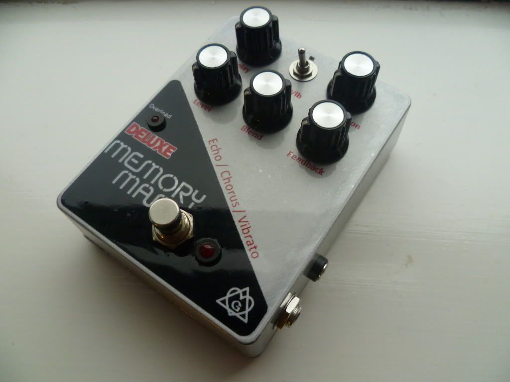
I found some time to start work on a decal now the box was drilled, and unashamedly went with a rip off of the original design. I love the 70s/80s EH designs, so why change a winning formula. Here is the prototype on paper.
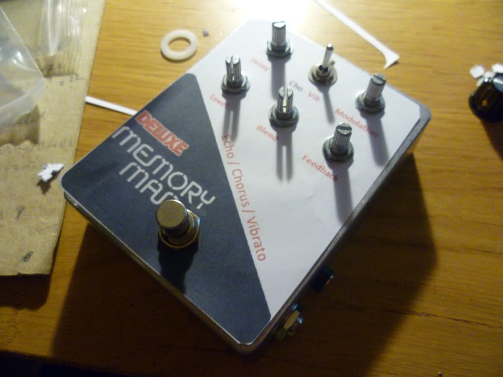
Afterwards I set about finalising this and making up the real decal. I use Inkjet Vinyl self adhesives, and clearcoat with automotive clear spray (3 coats). I sanded the box roughly at an 45 degree angle to simulate a brushed aluminium effect of the big trapezoid EH boxes. I think it looks nice.

Then came wiring up and testing outside the box. For those who follow the thread in Tech, this was time consuming and worrying, but eventually I am at the stage now where I have almost clean delays. Lessons learnt - socket all your ICs firmly. I didnt change anything than that between testing sessions. At first all I got was noise. Went away, had food, double checked all IC seating, and bam, some delay was coming through clean(ish).
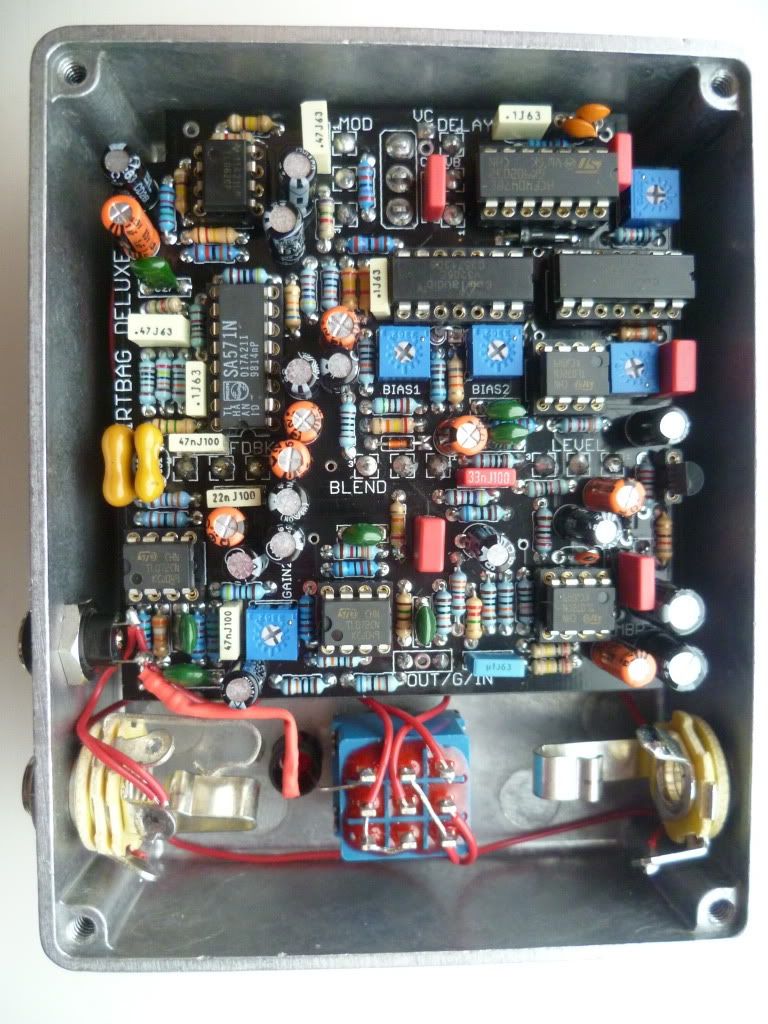
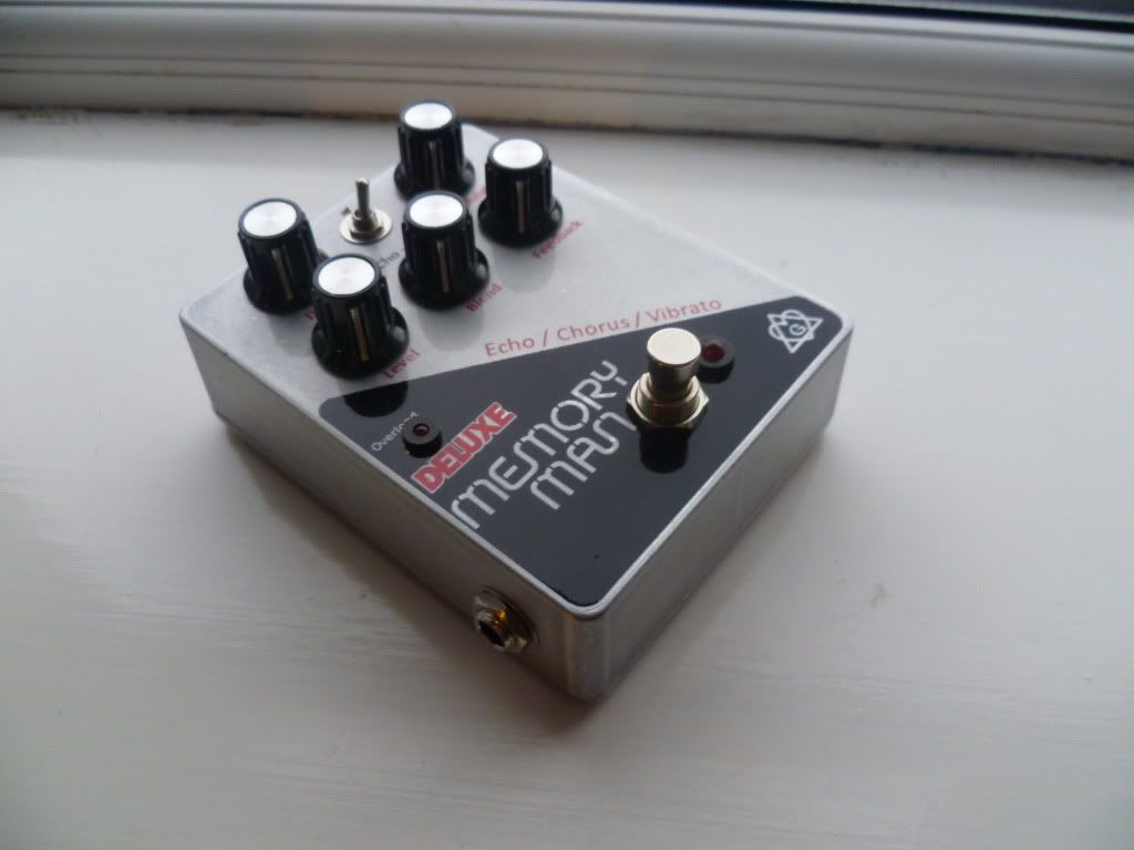
Anyway, this leads us to boxing-post-rocking. I used a 3mm red diffuse LED for the overload, and a 5mm red diffuse for the status, mounted in tayda holders. Hole sizes are 6mm and 8mm for these.

Pretty happy with the wiring job. The Power Jack placement was carefully measured before drilling to ensure clearance. In hindisight it would also been fine at the top centre near the VC connection, but I went with this and its fine. I used nice 8mm DC jacks. Perfect when you wouldnt use a battery anyway.
For the guyshot fans heres another close up
Finally, with the addition of some (in my eyes) lovely knobs, the thing is complete.
Thanks to Bean for the board, Scruffie for the tech help, and all others involved.
One hell of a project. Now to tweak and tweak and tweak those trimmers....
;DLS
Hi,
ReplyDeletenice work, well done!
What ICs did you went for in the end? MN3005s? Where did you buy them?
Cheers
Chris
Cool Audio v3205s got in a trade but they are commonly available.
ReplyDeleteWorth reading the forums at Madbeanpedals.com before embarking on the project.
Cool, thanks.
ReplyDeleteYour recommendation is well appreciated, especially since I ordered one (!) of these expensive mn3005s and afterwards recognized that I'd need two ... in the meantime the ebay seller vanished ... sorry for the story of my life :) ... merry Christmas
Chris
If you wanna sell the mn3005 or trade for some v3205 let me know I could use the mn3005...
ReplyDeleteWoah, just discovered your blog. This is awesome. Keep up the good work. I'm just getting into building pedals and this is a great resource. Cheers.
ReplyDeletewow, good stuff.
ReplyDeleteI'm considering having a go at one of these myself, what's a rough idea of cost including the IC's?
Hi.
ReplyDeleteBoard $15.
Case $7
Jacks and switch $6
Trimmers $1
Resistors $2
Caps $4
Pots $5
Standard op amps x 4 $2?
Clock ic and other funky $4?
MN3005 ??!! $60 a pair if you can find them so...
v3205 $16 the pair approx.
Total around $60 or £35 id estimate.
Good to hear from you, Happy New Year
Hi LaceSensor,
ReplyDeletenice work with the blog!
I'm planning to build a madbean DMM myself too, and I was wondering, which is/are the name/s of the font/s you used on your build?
Thanks
Nic
I cut up a high res image of a real one and used those.
ReplyDeleteIf you look on madbean some people made nicer efforts than me and shared the artwork.
Are you using mn3005 chips or v3205s?
good luck either way
Hi, thanks for the fast reply
ReplyDeleteI didn't find what I was looking for on madbean's forum, but I'm gonna have a deeper look tomorrow morning.
well, I still have to make my order on banzai
I think I'm gonna go with v3205
some people say they can hear the difference between the chips, some others say they almost can't...
Thank you again
Nic
Hi guys,
ReplyDeleteThat's a really tidy build there! Any have an idea where or who can provide one of these bare PCBs?