Also I reckon this is definitely a step up in the quality of work for me. Its my best build to date, and seeing as its the most recent, that does make common sense. However, my learning process has lead me to one massively important conclusion: It is incredibly important to plan plan plan check and plan again your proposed layout. I dont mean the circuit board, I mean the whole thing: location of the ins and out, location of the power supply, whether or not you want a battery, if so where will it go in the case? Where will the footswitch go? How close to the edge of the case? Do you want the body of the footswitch to act as a "cradle" for a 9v battery to stop it floating around in the case? Where will your circuit board go? How will you make sure it doesnt ground to any parts of the case? etc etc etc
As evident, this isnt an exhaustive list, but from my first build to this, that is the major concern that I have had to address. Otherwise, you soon realise, shit, my board wont fit anywhere, or its gonna touch something, or I dont have any room left for a battery. Anyway, you get the picture.
So, lets begin the build process. Firstly, selecting a circuit. Since I am still at the point of using Vero board, I didnt even considering buying a PCB, but there are commercialy available WM inspired designs, so if you fancy that route you can. Likewise, the Schem is on the net, so feel free to make your own Vero, Perf or other layout. Speaking of which, there are also a number of Vero layouts around. Furry Elephant, Prehistoric Fuzz bla bla. Anyway, I chose to use the freshly verified and beautifully compact layout here: IvIark's WM vero layout

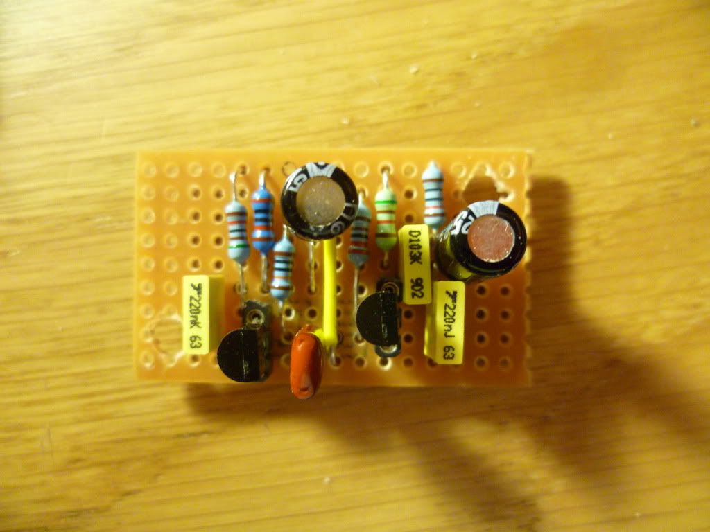
I stared with selecting the components I had to hand. Luckily (not really, cos Id planned, see, Im learning as above) I had the correct selection on components available. I did make one concession, as the 220nF cap in the layout on the right needs to strech over I think 5 holes. I had to get creative with some needle nose pliers to reshape the legs to fit. You can see the results below:
Here is my case, after I had carefully measured out, marked, and drilled for all the components:
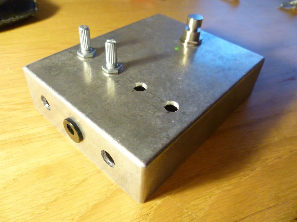
As I typically run all my effects by power supply, I want to get away from fitting batteries in my pedals. Also, I find the 9v snaps I have sourced to be of flimsy quality, and very hard to snap on and off a battery.
So, the next step was to fill up the interior of the box to check everything fitted. I took this time also to plan where I would stick the board down. This resulted in me deciding to use a craft knife to "trim" the square sticky feet of the standoffs I bought. You can see this below, hopefully:
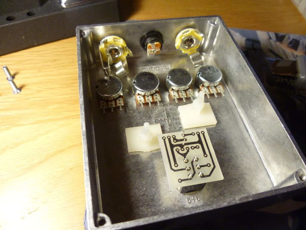
Theres loads of room in this case to make a neat and tidy job of the wiring. I have been insipired by some top end builders to try my best with the internal wiring. I have found that solid core hookup cable works the best, and Im using nice different colours from Doctor Tweek for this purpose.
With everything in place, its time to start figuring out the lengths of wires needed to reach from the pots to the board, and then assembling in situ the pots with all the wiring in place, before soldering. I think this is a good way to acheive a neat finish without excess cabling (aka birds nest / bowl of spaghetti) that seems to result from wiring up on your desk, then stuffing into a box, without measuring properly.
So, this is the start of that process for the potentiometers:
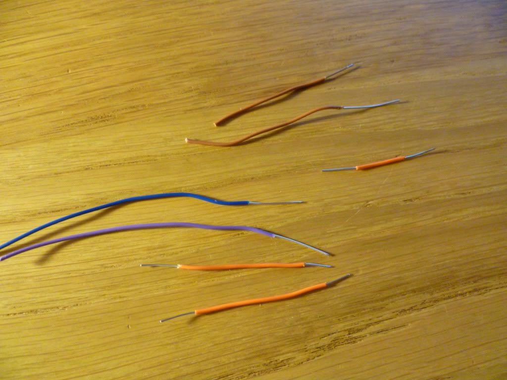
As you can see depending on the connection, I like to trim between 1 to 2 cm of insulation from the cable. This is the fed through the eyelet hole at the top near the body of the pot, down to the tang or sticky out bit or lug whatever it is called. I then, in the case of a single lug connection, bend the cable around the lug and back upwards. This can then be soldered and trimmed. In the case of a pot that required a lead to both lugs (in essence a jumper) I use the longer trimmed insulation part, thread through as above, but then after looping round the first lug, jumper it over to the next lug and fold it round again. This provides secure connection, and although the wire goes through the hole, we arent actually soldering at the hole, which as noted might heat-damage the carbon tracks of the potentiometer.
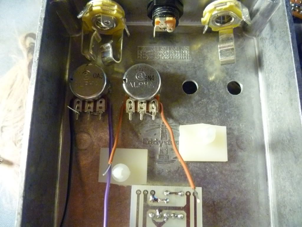
Here is how the first pot in place looks in the build. Note, this is the Wool pot.

The schematic then asks for lug 2 and 1 to go to ground. The black wire is run behind the pot, up through the hole for lug 2, round the left of lug 2, up over lug 1, then wrapped up and around lug 1 securely. I should note the wiring positioning is done outside the case. I then drop the pot shaft through the correct drilled hole (7mm in the case of these 16mm pots) and then secure with the washer and nut.
As one would expect, this process is complicated slightly when you require jumpers between lugs of two (or more) pots. Using my method, you have to arrange this off the deck so to speak, then transfer two or more pots to the enclosure, which can get a bit fiddly. I think its worth it though.
Here is the next pot, Pinch. Ive used brown wire, its yellow in the schematic. This one is quite simple.
Third pot is the EQ pot. This one needs to be connected to the Output pot. I acheive this by carefully measuring how long the jumper between pots needs to be, then placing the assembled pot into the case. The last pot on the right (Output/Volume) can then be lowered into the drilled spot, and on the way down feed the wire through the correct lug hole.
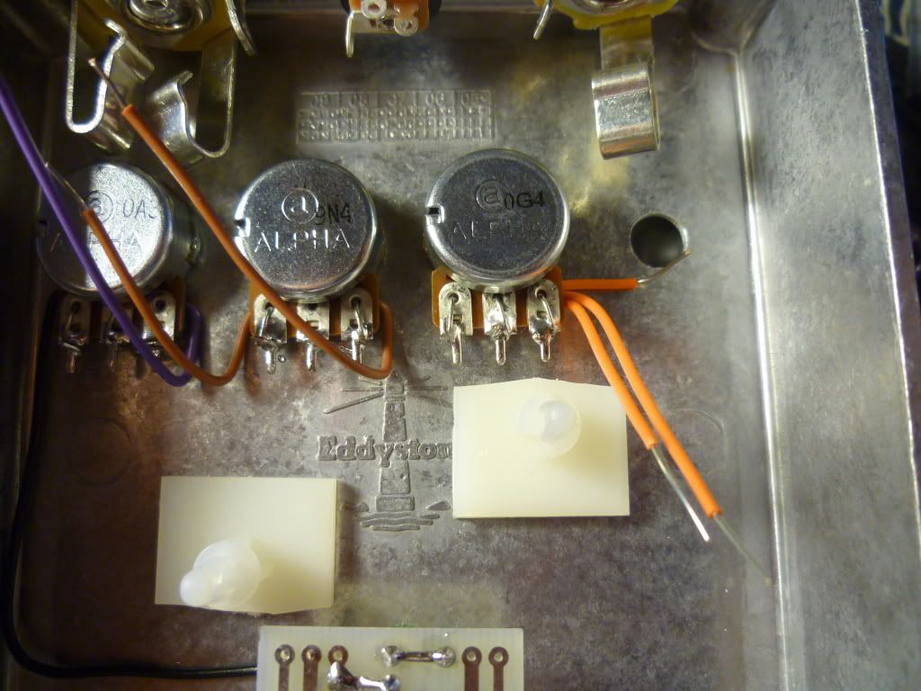
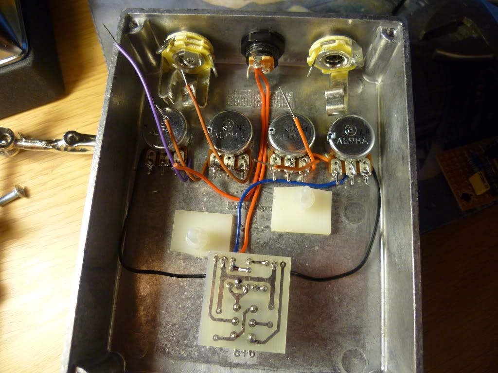
So, the fourth pot in place no, and the keen eyed will see that Ive been doing some soldering in parallel.
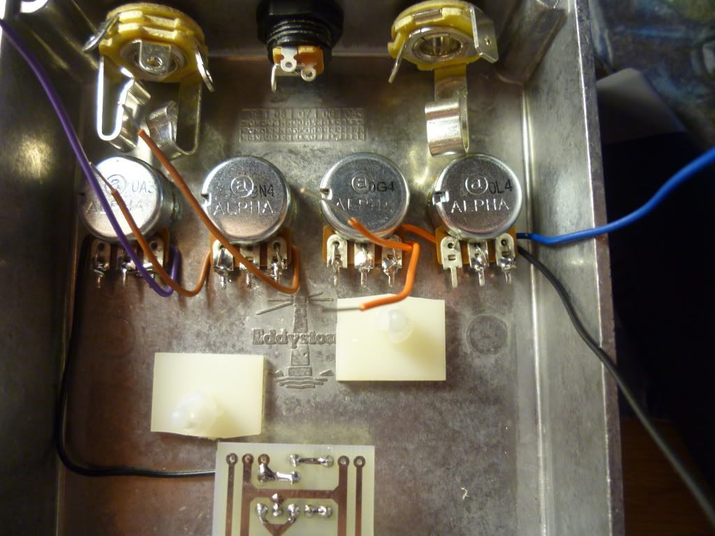
Here you can see the link (orange cable) coming from the EQ pot across to lug 3 of the Output pot. I havent yet fixed this into place yet. Every other pot connection is soldering in place. Black is ground on both the rightmost and leftmost controls. Navy blue is the circuit output, which in time will be wired to my DPDT switching assembly.
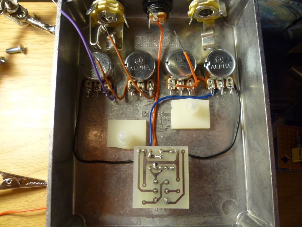
The picture below shows the start of the process for wiring everything to the footwitch assembly. You can refer to my FF build for some more info. I'm using a nattily designed and perfectly crafted DPDT daughter board incorporating LED, LED reistor and Millennium bypass circuitry. This shot shows the first of two 9v connections (this one going to the Millenium board, the second one coming later needs to feed the circuit board itself). I have also wired in two of the ground cables, and the circuit output from the Volume pot (blue).
Incremental next step - wire in the second 9v cable (red)
Then its time for really big job. I didnt document this too well as I was too busy concentrating. Basically, we need to make the "offboard" connections to the actual WM circuit board. There are 8 in total, referring back to the schematic above. The orange wires, purple wire, and right most brown wire need to come to the right hand side of the board. I did these first. Then with the board at about a 45 degree angle to the enclosure, I did the connections to the right hand side: +9v power, Input (green) the other brown wire, and the ground (black).
See here for my results:
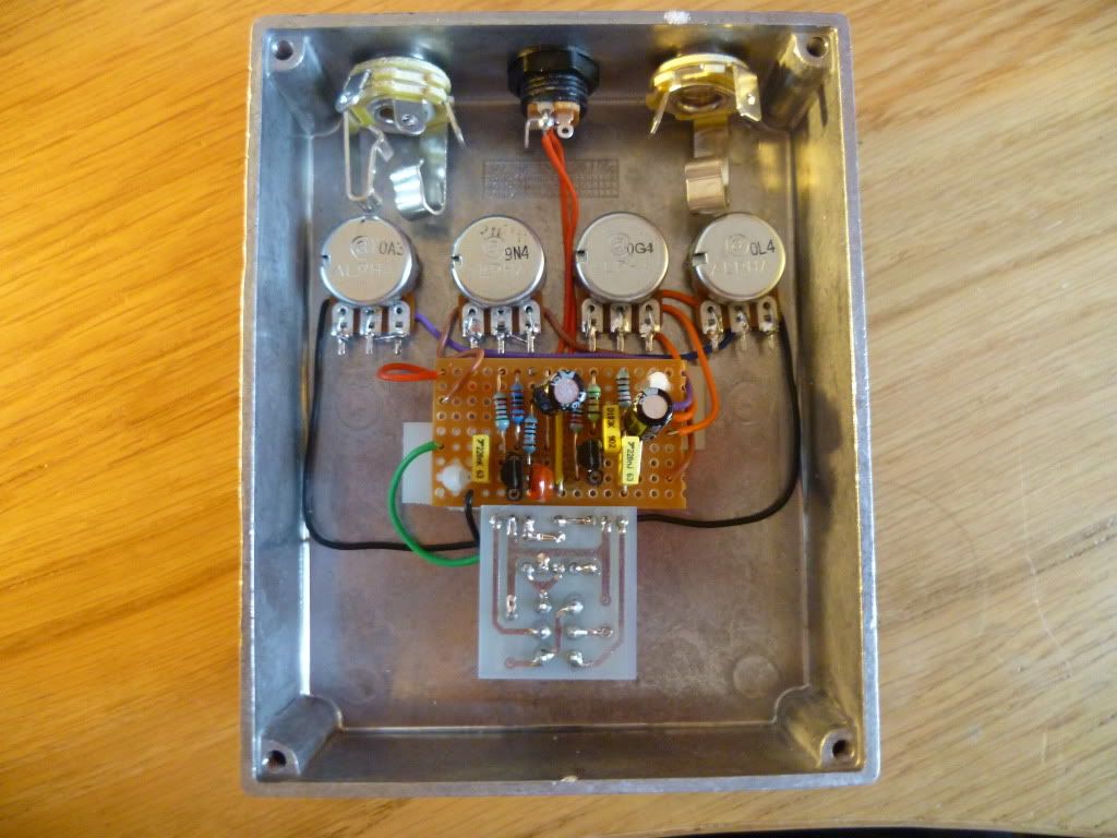
So, we are now at the point where 3 of 4 grounds are wired, the board is in place, the board in and outs are wired, everything that should have power is connected, so whats left?
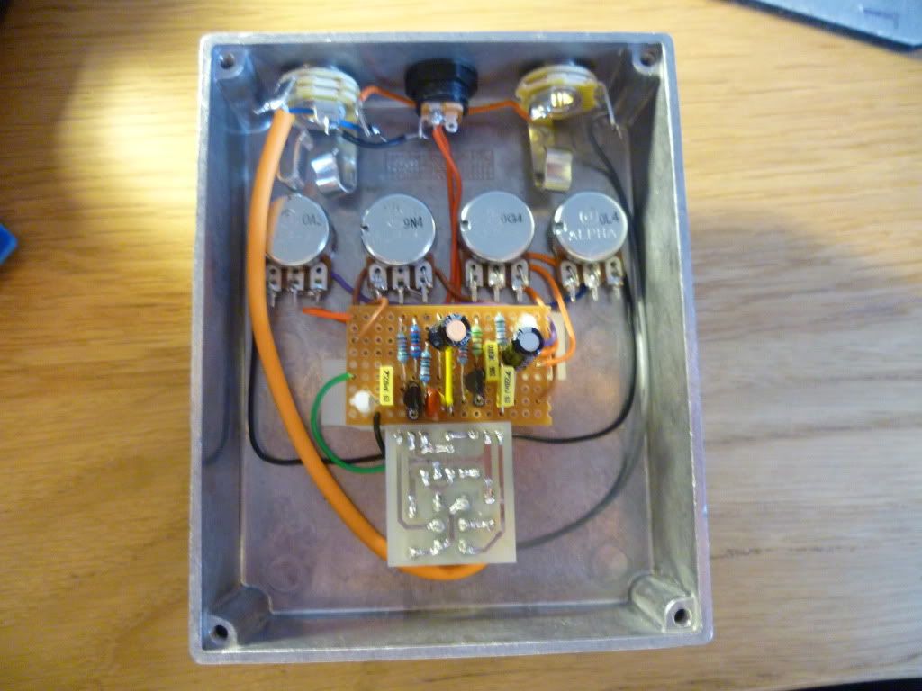
Well, we need to connect a ground from the pots. I do this by firstly jumpering the ring of the Mono out to the sleeve of the Stereo out, and then using one of the cores of a screened cable, run that to the last of 4 ground points on the Millenium DPDT board. I also need to connect the "-" side of the 9v 2.1mm connector to the ring of the Stereo In jack. Lastly, we need to wire the guitar jack In and Out to the footswitch. For the output, I've used a standard grey wire. For the input, I've used the other core of a screened cable (Van Damme, from Doctor Tweeks). It's the neon orange part, you cant miss it.
So we end up with this:
All told this project took me around 6 hours to put together. I started around 5pm - 6pm making the vero board. Then from about 7pm (after food :) ) with the layout, drilling and positioning. Then into the night up til 1am was soldering. I got to the point where I only had the input output and grounds to do. That took me about 20 mins the next day.
The result, avec some nice MXR style knobs, is this:
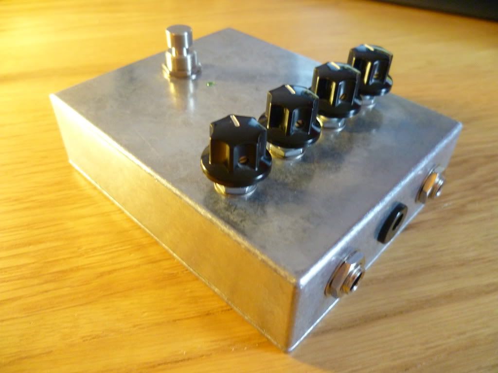
I made a very quick video. Apologies for the sound, it seems my hand was covering the mic at various points, and when I was turning and naming the controls. It sounds absolutely huge, buckets of bass. Sounds awesome on either bass or guitar. The end riffs I played were with a more trebly setting. Beleive me, this is fat fat fat. Kicks the ass of the Big Muff NYC I used to own (was lost or stolen at a gig, lent to bass player :( )
Heres the video
As you can see the green LED is plenty plenty bright! I wont rant more on superbright LEDs but I think ill be using 50k resistors on my remaining ones (!!)
Comments feeback questions Ill do my best to answer :D
Ooh think you've got the pot numbering back to front on a couple of the pots mate. Looking at the back of the pot with the lugs pointing downwards, the numbering would be 3, 2, 1 from the left, exactly as shown in the layout.
ReplyDeleteSo it looks like the Wool and EQ pot are backwards, but the Pinch and Volume are correct I think?
Its 100% as the layout.
ReplyDeleteJust to confuse matters I have realised the way I wrote the description was 1 2 3 from left to right. I will have to edit.
But in terms of how its wired, its absolutely as yout layout, and the sounds are identical to my ears to the youtube videos of the real thing.
quick ninja edit performed. Should read correctly now. Some of it looks like its wired wrong too, but I have simply been creative in which direction I sent the wires to suit where the wire needs to end up (left or right of the circuit board). That is of course hidden by the bottom part of the pot.
ReplyDeleteHa ha I wondered why it only looked backwards in two of the pots! :o)
ReplyDeleteWhat do you think of this method for wiring up the pots?
ReplyDeleteI find it really tricky to just hold the wire to the lug and solder them together, and it seems unstable to me.
any thoughts?
It looks like a good method to me. I've seen people recommend against soldering to the hole in each lug but I can't see anything wrong with using the hole to keep the wire steady. I too never felt comfortable in tack soldering point to point so I tend to use a small piece of vero when I'm using PCB type pots (which is most of the time because they're so cheap from Futurlec). Like this:
ReplyDeletehttp://i76.photobucket.com/albums/j6/IvIark_2006/DIY/13112010424_2.jpg
Vero is so easy to solder to that it makes it a breeze, plus it also acts as a heatsink when soldering so you can't really feel any heat transferred to the main body of the pot.
Hmm looks like a good alternative.
ReplyDeleteI quite like my method and it seems to work too :)
I`m not sure if you wrote it somewhere, cause my english isn`t perfect (I`m from Germany)but... what exactly does it costs to build it and what do i have to buy? I know it is a lot of work but..could you make a list of everything? :S
ReplyDeleteHi thanks for th comment. Basically the schematic is in one of the photos above. You wil need all those parts, plus a box, input and output jacks, vero strip board, a dc adaptor jack, and battery snap, plus your choice of led and footswitch. The are plenty of websites for this see my links on the right hand side of the blog. As you are in Germany a perfect website is banzaimusic.com. I think I have a link for is too, otherwise google banzai music, they are based in Germany. Any further queries, just ask. Enjoy the blog and building your mammoth
ReplyDeleteHi!
ReplyDeleteI'm a beginner builder, and I have to say, your blog is fantastic!
What inspired me to build was the ridiculous price of the Z.Vex Woolly Mammoth, so great to see how to build one for myself.
The only thing I am a little hazy on is the wiring for the millennium bypass. I can't see what is soldered onto the board, I have seen diagrams on Ivlark's blog about wiring the millennium bypass but how do you wire all those grounds to it?
Thanks!
- Chris
Hi
ReplyDeleteIts using a special board, I dont think its required. I would simply recommend a blue 3PDT switch, and there are many wiring plans around.
the best is (IMHO) here http://www.madbeanpedals.com/tutorials/downloads/StandardWiring_MBP.pdf
Thanks a lot! That helps!
ReplyDeleteAlso, how do you go about selecting your capacitors? I have seen gut shots of a few Woolly Mammoth copies and everyone uses different ones, what would you recommend?
Thanks again!
For the charged ones, you want 16v or greater Electroltyics, I like radial ones, just spread the legs (ha!) For the non-polar type, I use 5mm poly box caps. you can source all these using the links on my blog page top right. GL
ReplyDeleteHey, I'll make the mammoth...
ReplyDeleteI'm surprise about your resistors's values. Had you changed the schematic data ?